
Step 4 – Let’s try it! Hit the normal “Icon Menu” icon to insert components. Hit “OK” and “OK” to get all the way out of the Icon Menu Wizard tool. Put a space between each symbol name as shown below. Miniature Circuit Breakers (MCB) Low-voltage Circuit Breakers Low-voltage Power Distribution Products CAD Data Downloads MITSUBISHI ELECTRIC FA Low-voltage Power Distribution Products - Low-voltage Circuit Breakers Dimensions/CAD About copyright, and the operating environment, notes Miniature Circuit Breakers (MCB) loading. Type in the child symbol name four times. Type in the parent symbol name (from step 1 above). Here is where we trick AutoCAD Electrical to insert five poles (1 parent + 4 child symbols). This brings us back to the previous dialog below but has filled in the “Command” edit box with command name WD_3UNIT. Pick on the 3-pole parametric build option (even though we want 5 poles). … the dialog below shows the standard commands available for the icon menu. Okay, here we are at the desired page… dealing with breakers and switches.įill in some data on the form for the new icon… This is where we’ll add our new 5-pole CB icon. Step 3 – Drill down to the Circuit Breakers / Disconnects icon menu page. Step 2 – Launch AutoCAD Electrical’s Icon Menu Wizard tool. … and the block name used for the 2+ child poles. Then use any block/attribute editing tool or the AutoCAD “LIST” command to get the block name of the top symbol (the parent)… Just insert a 3-pole breaker from the icon menu somewhere in space on the drawing. Step 1 – Determine the parent and child symbol names needed to build the breaker. Here’s a step-by-step sequence showing how to add a new button to the icon menu for a 5-pole circuit breaker. Normally, to accommodate a circuit breaker of more than three poles, you pop in the 3-pole breaker from the stock icon menu pick and then manually add in to more single child breaker poles.īut let’s say that we routinely need to insert a 5-pole circuit breaker…

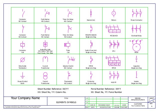
Now you'll be asked to select a menu file, we're using schematic drawings, not panel drawings so we select Schematic there and it brings up the DAT file, the default DAT file, now we're using NFPA standards as well so you can see that that's the NFPA menu.DAT file I'll click on OK, also I've done that, the Icon Menu Wizard comes up and it looks remarkably like the icon menu that you used to insert symbols into your schematic drawings.The icon menu component insertion tool can be easily customized to extend quick pick and dynamic insertion of multi-pole devices of pole counts beyond AutoCAD Electrical’s 3-pole default.

So we'll keep the control.dwg file open, go to the Schematic tab on the ribbon and you want to go to the other Tools panel here and select Icon Menu Wizard.

What we're going to look at now is customizing the Icon Menu to add our custom symbols to it so they can be used over and over again. We're staying in our control.dwg file in our Project 004, and what you can see there that I've done is zoom extense, there's our custom symbol that we brought in the previous video.


 0 kommentar(er)
